Translation notice
This page was translated with machine translation and may contain inaccuracies. If you can help improve it, please open an issue or submit a pull request.
Shader Practice - Accurate Sampling Texture
summary
This article provides a method for sampling surface textures stably and accurately. The original numerical stability problem is solved to facilitate the shader to obtain additional information on the texture.
Preface
The topic to be discussed in this article is not how to sample and then display colors. This has already been introduced in the core shader workflow, and more in-depth sampling theory will be introduced in other topics. The issue considered in this article is how to accurately obtain the texture information attached to this surface in the fragment shader.
In the previous "Shader Practice - Code Rain Block" and "Shader Advanced - Physically Based Rendering (PBR)", we introduced a way toTransformation, a method of converting the normalized texture coordinates in the plane into sprite coordinates for sampling. However, the partial derivatives used in this method have numerical stability problems, and noise will be generated during sampling, resulting in distorted results.
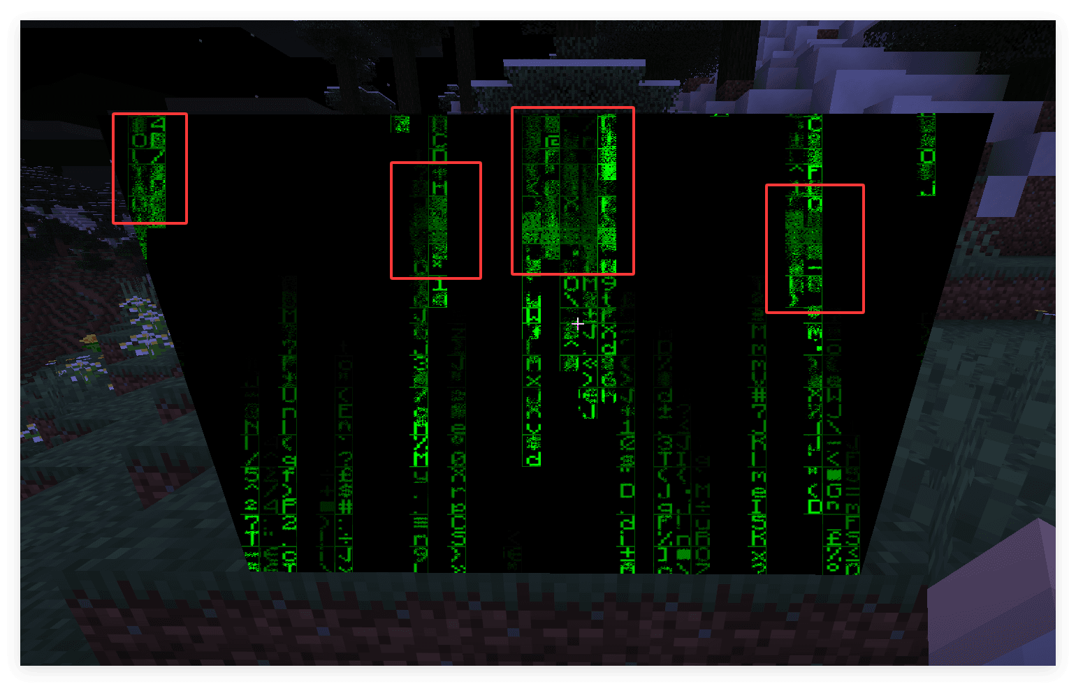
Therefore, we hope to use a more stable sampling method to accurately sample according to the given normalized texture coordinate.
Calculated by texture resolution
It would be easier if we knew in advance what the resolution of the texture would be. We record the size of the material asvec2 imgSizeorivec2 imgSize(We usevec2A little more, since it's better suited for interpolation and computation).
Our goal is to use normalized coordinate sampling in the context of any fragment, and we also need to know the size of the texture atlas. The size of the texture atlas is actually the size of Sampler0. We can directly passvec2 atlasSize = textureSize(Sampler0, 0)Get. (The second parameter is Lod)
Then normalized coordinateimgCoordThe actual sampling coordinate of the corresponding Sampler0 is the starting point coordinate plusimgCoord * imgSize / atlasSize
Next we calculate the coordinates of the starting point. Examining any patch, we can obtain its normalized coordinate within the plane using a similar method as before.vec2 normalizedUVand interpolatedtexCoord0, and the same logic as above, there is a relationship heretexCoord0 = startCoord + normalizedUV * imgSize / atlasSize
Apart fromstartCoordare all known, sostartCoord = texCoord0 - normalizedUV * imgSize / atlasSize
So we get a mapping from the normalized coordinate to the actual sampled coordinate of Sampler0
vec2 imgSize = ... ;
vec2 atlasSize = textureSize(Sampler0, 0);

vec2 startCoord = texCoord0 - normalizedUV * imgSize / atlasSize;
vec2 sampleCoord = startCoord + imgCoord * imgSize / atlasSize;
After simplification
vec2 imgSize = ... ;
vec2 atlasSize = textureSize(Sampler0, 0);

vec2 scale = imgSize / atlasSize;
vec2 sampleCoord = texCoord0 + (imgCoord - normalizedUV) * scale;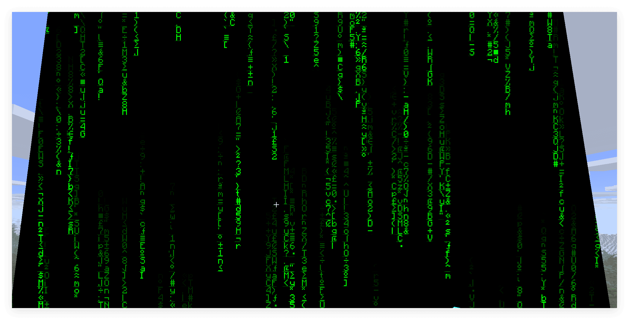
You can see that the noise disappears and the sampling is very clean.
Things to note
The arrangement of vertices and sample coordinates may change between different versions of Minecraft (in fact, Mojang did change it several times). make surenormalizedUVThe surrounding direction oftexCoord0consistent.
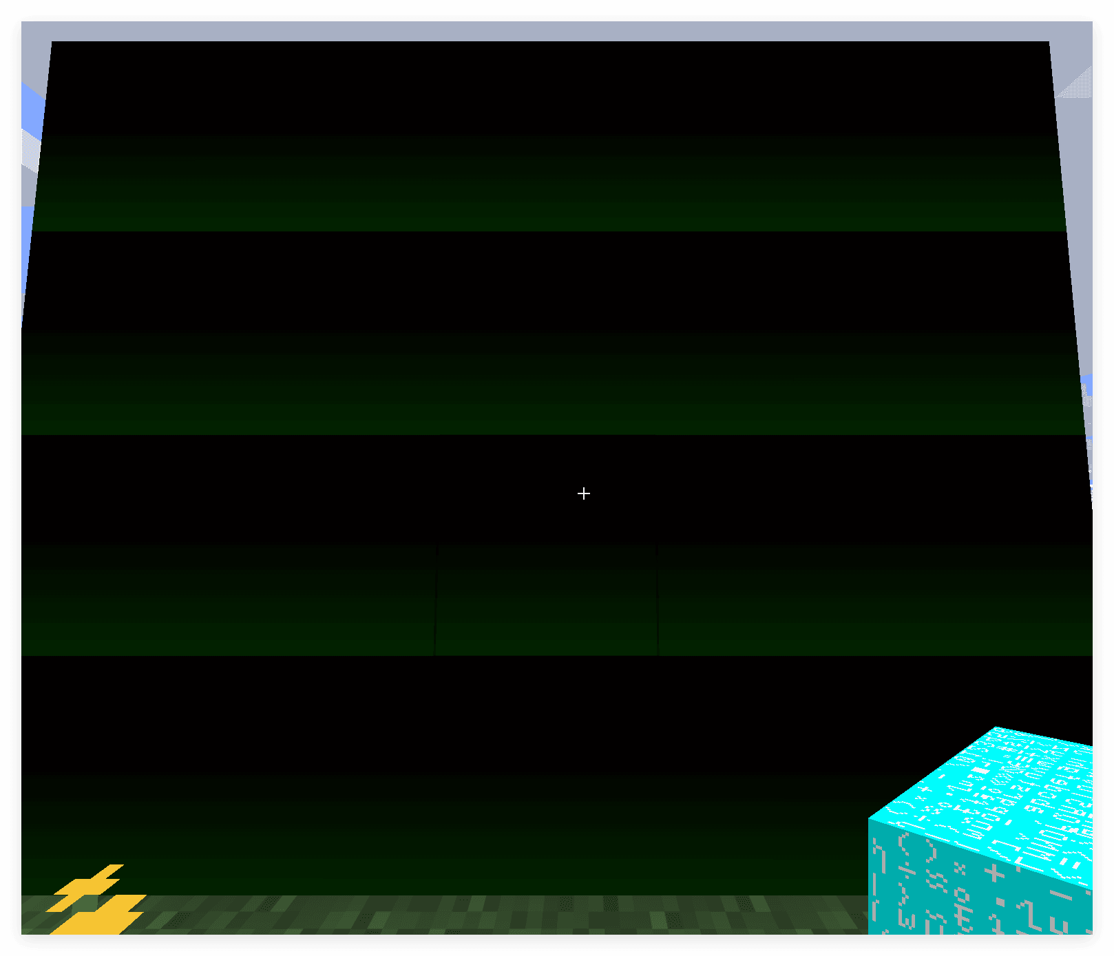
In the previous model we had the relationshiptexCoord0 = k * normalizedUV + b, herek = imgSize / atlasSize b = startCoord, if the wrapping directions are inconsistent, outputstartCoordYou will see that b changes linearly in a certain direction. The figure below shows whentexCoord0Taking the upper left corner as the origin, andnormalizedWhen taking the lower left corner as the originfragColor = vec4(startCoord, 0.0, 1.0);the output result.
More examples will be shown in the subsequent "Shader Practice - Grayscale and Dithering".