
Translation notice
This page was translated with machine translation and may contain inaccuracies. If you can help improve it, please open an issue or submit a pull request.
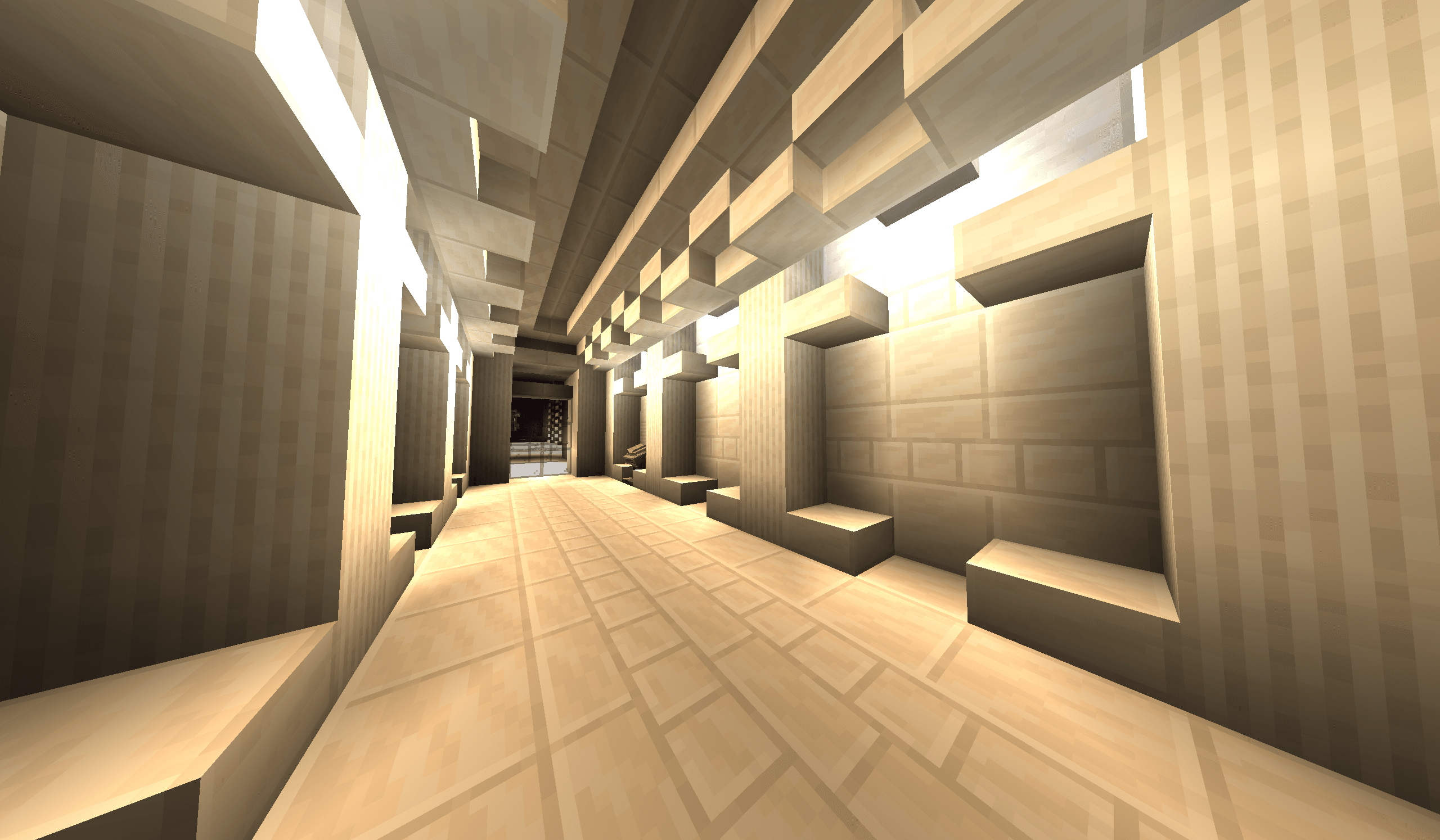
Shader Advanced: Physically Based Rendering (PBR)
Preface
Although this article was not planned, since I have published related videos on station B and received many inquiries from readers, I decided to add this part of the content. It must be noted that the relevant knowledge of PBR has little to do with Minecraft. Most of it is general and possibly boring computer graphics content. Readers can choose to read according to their interests.
In addition, the release time of the shader series tutorials does not determine the learning sequence. After the tutorials are basically completed, readers can find the editor's learning sequence guidance in the resource pack system module of the main website. It is recommended that readers learn the Blinn-Phong lighting model first, and then learn PBR content. I may write an article about the Blinn-Phong model in the future.
Introduction to PBR
In fact, most readers have come into contact with PBR textures, but they may not know the specific meaning of PBR. The full name of PBR is Physically Based Rendering, which is physically based rendering. It is a rendering method that achieves more realistic visual effects by simulating the physical process of light interacting with the surface of an object. Therefore, PBR is mainly divided into two parts, namely the lighting model and the texture model, which we will introduce separately.
rendering equation
The core of PBR is the rendering equation (Rendering Equation), which describes how the outgoing light (Radiance) of each point on the surface is determined by the incident light (Irradiance) and texture attributes. The integral form of the rendering equation can be expressed as:
is a point on the surface,It’s the outgoing light,It's self-luminous,is the bidirectional reflection distribution function (BRDF),is the incident light,is the normal line,andare the incident and exit directions respectively.
The integral part represents the contribution of all incident light to the outgoing light. However, in Minecraft our light sources can all be regarded as point lights, so the integral can be simplified to the sum of all light sources:
The self-illumination term in the formula is easier to understand, andIt is the incident light intensity calculated based on Lambert's cosine law. We have introduced it in the previous basic tutorial. Simply put, the irradiance of the incident light on the surface is proportional to the cosine of the angle between the incident light intensity and the normal (i.e.), also related to the intensity of the incident light itself at this point, that is, function
one remaining itemIt is the core content of PBR - bidirectional reflection distribution function (BRDF). It describes how a surface reflects incident light in all directions. BRDF is usually modeled based on physical properties. Common models include Lambertian (diffuse reflection), Cook-Torrance (specular reflection), etc. We introduce here the more complex and realistic Cook-Torrance model.
Basic theory
Microfacet Theory
Microsurface theory believes that there is no completely smooth texture, and an extremely smooth texture has small bumps and convexities on its surface. Reflection, refraction, and scattering of light will occur on these uneven surfaces. When the microsurface is rough, the reflected light will be more dispersed, resulting in diffuse reflection. When the microsurface is smoother, the reflected light will be more concentrated, resulting in specular reflection.
Helmholtz reciprocity theorem
In a non-absorbing medium, the propagation directions of light waves can be interchanged without affecting the intensity distribution. That is, when the exit angle and incident angle are interchanged, the BRDF value does not change (in actual situations, the BRDF model may violate this rule).
Energy Conservation
Conservation of energy is one of the basic rules of physics, and in rendering, it manifests itself in the fact that the outgoing light is never greater than the incoming light. This means that the sum of the texture's reflectance and transmittance cannot exceed 1.
In addition, during the propagation process of a point light source, the light energy contained in a spherical shell with the light source as the center is constant, which means that the relationship between the light radiance received per unit area of the spherical shell and the distance is an inverse square law.
In rendering, energy conservation is not necessarily strictly followed, but is pursued approximation to avoid excessive objects and unrealistic look and feel.
Directional-Hemispherical Reflectance
Directional hemispheric reflectance is often referred to as DHR, orexpress. The directional hemisphere refers to the hemisphere centered on the normal. The DHR describes the overall reflectivity of the surface that reflects light onto the hemisphere. It describes the degree of conservation of the BRDF model. According to the law of conservation of energy, the value of the directional hemisphere reflectance must be between 0 and 1. can be defined as, similarly, due to Helmholtz reciprocity, it can also be defined like this. In fact we have already seen this part in the reflection equation.
Fresnel Reflection
Light is reflected and refracted on the textured surface, and Fresnel reflection describes the ratio of reflected light to refracted light. When the viewing angle is perpendicular to the surface, less light is reflected, and when the viewing angle is closer to parallel to the surface, more light is reflected.
Lambert's Cosine Law
For a surface perpendicular to the illumination direction, the amount of light radiation received per unit area is 100%, and when it is at an angle of 60° to the illumination direction, this ratio is reduced to 50%. That is, the amount of light radiation received by the surface is proportional to the cosine of the angle between the normal and the direction of illumination, which is called Lambert's cosine law.
Since we have already introduced this term in the reflection equation, we no longer consider it in the BRDF model.
Cook-Torrance BRDF
Based on the above theory, Robert L. Cook and Kenneth E. Torrance proposed a BRDF model based on microsurface theory, called the Cook-Torrance model. This model decomposes the BRDF into three main parts: the microsurface normal distribution function (D), the geometric occlusion function (G), and the Fresnel reflection term (F). The expression of Cook-Torrance BRDF is as follows:
in,andare the weight coefficients of diffuse reflection and specular reflection respectively, satisfying, determined by specific texture properties.is Lambertian BRDF, representing the diffuse part:
In fact, Lambertian BRDF is a constant function, meaning that the surface reflects light uniformly in all directions.is the diffuse color of the texture, the denominator ofIt is to ensure the conservation of energy. (That is, the directional hemispheric reflectivity does not exceed 1)
$ f_{\text{cook-torrance}} $It is the specular reflection part of the Cook-Torrance model, defined as:
Likewise, the denominator ofIt is to ensure the conservation of energy.
inThey are all functions related to texture properties and lighting geometry.
Microsurface normal distribution function (D)
Microsurface normal distribution functionDescribes the microsurface normal (that is, the normal of the tiny bumpy surface) relative to the macro normal (normal map)distribution. Commonly used distribution functions include the Beckmann distribution and the GGX distribution. Here we use the GGX distribution, which is defined as:
in,is the half-range vector, that is, the normalized vector between the incident direction and the exit direction, which can be directly obtained by normalizing the sum of the two vectors.is the roughness parameter, the value range is, indicating the roughness of the surface,means completely smooth,Represents a very rough texture, determined by the texture properties.
Geometric masking function (G)
Geometric masking functionOcclusion and shadowing effects between microsurfaces are described. A commonly used geometric masking function is the Smith function, which is defined as:
That is to say, the shielding in the incident direction and the outgoing direction is considered to be independent.is the one-sided geometric shading function, and the product of the two directions is the total geometric shading function.
Defined under Schlick approximation as:
in,,Can be the direction of incidenceor exit direction。
Fresnel reflection term (F)
Fresnel reflection termDescribes the ratio of light reflected and refracted on a surface. A commonly used approximation method is the Schlick approximation, which is defined as:
in,is the reflectance at normal incidence, usually determined by texture properties. For non-metallic textures,Typically lower (like 0.04), whereas for metallic textures,Higher (e.g. above 0.9).
Combined BRDF
Combining the above items, we get the complete Cook-Torrance BRDF. It can be seen that these formulas are empirical formulas and are not strictly derived based on physics. However, they are a good approximation of the lighting phenomenon in the real world. They are also easy to calculate and suitable for real-time rendering.
The final Cook-Torrance BRDF can be used in the rendering equation to calculate the outgoing light of each fragment. This is the core content of the PBR lighting system.
Texture system
In the above formula, the modifiable parameters include:
- diffuse color: Determines the base color of the texture.
- Roughness: Determines the smoothness of the texture surface and affects the diffusion of highlights.
- Metallicity: Determines whether the texture is metal or non-metal, affecting the Fresnel reflection termvalue.
These parameters can be obtained from three different texture maps, namely Albedo Map, Roughness Map and Metalness Map. The workflow based on these three maps is called Metalness-Roughness Workflow.
In addition, 3 auxiliary maps can be added:
Normal Map: used to represent the macroscopic normal distribution of the surface, affecting the normals in lighting calculations. Since color values can only represent positive values, the colorThe actual corresponding normal is。
Ambient Occlusion Map: Used to represent the degree of ambient light occlusion on the surface, which is directly multiplied by the outgoing light to affect the overall brightness.
Parallax Map (Parallax Map): used to simulate the slight bump effect on the surface, affecting the offset of the texture sampling coordinate, thereby enhancing visual details.
shader implementation
TBN matrix and tangent space
The tangent space is a local coordinate system established based on the surface of the model. It usually consists of three orthogonal vectors: normal, tangent and bitangent. The establishment of tangent space is crucial for the correct application of normal maps, because the normals in normal maps are defined relative to tangent space.
In the vertex shader, Minecraft already provides the vertex attribute Normal, while Tangent and Bitangent need to be calculated by ourselves, which needs to be calculated through partial derivatives in fsh.
passdFdxanddFdyfunction, we can calculate the partial derivative of texture coordinate in screen space, thereby calculating the tangent vector. The mathematical proof is given in the appendix:
vec3 dp1 = dFdx(worldPosition);
vec3 dp2 = dFdy(worldPosition);
vec2 duv1 = dFdx(uv);
vec2 duv2 = dFdy(uv);
vec3 tangent = normalize(duv2.y * dp1 - duv1.y * dp2);
NOTE: Extreme values may need to be handled
After getting a tangent line, we regard it as the main tangent line, and then calculate the secondary tangent line through the cross product:
vec3 bitangent = normalize(cross(normal, tangent));Finally, we combine the normals, tangents, and paratangents into a TBN matrix:
mat3 TBN = mat3(tangent, bitangent, normal);This matrix can convert vectors from tangent space to world space.
By sampling the normal map, we can get the normals in tangent space, and then convert them to world space through the TBN matrix:
vec3 n_tbn = ... // 这是从法线贴图采样得到的切线空间法线
vec3 n_world = normalize(TBN * n_tbn);
Sampling techniques
Since Minecraft's shader can usually only access one modifiable texture, and this texture is embedded in the sprite map, we need to merge multiple textures into one texture for sampling, and establish the texture coordinate mapping relationship on the submap.
The techniques used are proven in "Shader Practice - Code Rain Block", and the code examples are given directly here:
// 在 vsh 中计算
out vec2 NormalizedUV;
if (gl_VertexID % 4 == 0) {
        NormalizedUV = vec2(0.0, 1.0);
    } else if (gl_VertexID % 4 == 1) {
        NormalizedUV = vec2(0.0, 0.0);
    } else if (gl_VertexID % 4 == 2) {
        NormalizedUV = vec2(1.0, 0.0);
    } else {
        NormalizedUV = vec2(1.0, 1.0);
}// 在 fsh 中计算
in vec2 NormalizedUV;
vec2 k = dFdx(texCoord0) / dFdx(NormalizedUV);
vec2 b = texCoord0 - k * NormalizedUV;
vec2 SpriteUV = k * SpriteNormalizedUV + b; // 这一行在最终采样时使用,我们提供的 SpriteNormalizedUV 是子图内的归一化坐标,通过计算可以得到正确的采样坐标.Get the lighting direction
Since the light source position is not provided in Minecraft, we need to back-solve the lighting direction through the diffuse reflection intensity in the vanilla Lambert model. (Note that the accuracy given by this solution is very low. The common implementation method is to go to the post-processing shader to achieve the PBR effect, but here we try to implement it in the core shader)
The sampling results of the lightmap are given by the following code (extracted from vanilla vsh)
vec4 minecraft_sample_lightmap(sampler2D lightMap, ivec2 uv) {
    return texture(lightMap, clamp((uv / 256.0) + 0.5 / 16.0, vec2(0.5 / 16.0), vec2(15.5 / 16.0)));
}

minecraft_sample_lightmap(Sampler2, UV2) // 该函数返回的是光照的颜色和强度,相当于 L_i(p, ω_i)项
In order to make the lighting information obtained by sampling more accurate, we modify lightmap.fsh, set the ambient lighting color and sky lighting color to white, and cancel the flickering effect of block lighting (if you need to retain part of the vanilla lighting effect, design and modify it yourself):
// lightmap.fsh
// 完整的修改不给出, 这里介绍如何修改

layout(std140) uniform LightmapInfo {
    float AmbientLightFactor; // 使用该变量的地方替换为 0.0
    float SkyFactor; // 设为合适的定值
    float BlockFactor; // 设为合适的定值
    float NightVisionFactor;
    float DarknessScale;
    float DarkenWorldFactor;
    float BrightnessFactor;
    vec3 SkyLightColor; // 使用该变量的地方替换为 vec3(1.0, 1.0, 1.0);
    vec3 AmbientColor; // 若 AmbientLightFactor 保留,则使用该变量的地方替换为 vec3(1.0, 1.0, 1.0);
} lightmapInfo;
Note: If you need to preserve the color, you can refer to the technique of encoding more information in the texture, which I will introduce in next month's article.
Similarly, by performing partial derivative calculation on the return value of minecraft_sample_lightmap(), we can get the lighting direction described in world space:
vec3 lightColor = minecraft_sample_lightmap(Sampler2, UV2).rgb;
vec3 dp1 = dFdx(worldPosition);
vec3 dp2 = dFdy(worldPosition);
vec3 dl1 = dFdx(lightColor);
vec3 dl2 = dFdy(lightColor);
vec3 lightDir = normalize(cross(dl2, dp1) - cross(dl1, dp2));
NOTE: Extreme values may need to be handled
Now that we have the normal, lighting direction and viewing angle direction (that is, the position vector of the fragment in the view space is inversely normalized), and then sample the roughness, metallicity and diffuse color, we can substitute these values into the Cook-Torrance BRDF formula to calculate the final emitted light color.
The final color is multiplied by the value of the ambient occlusion map to get the final fragment color.
Parallax map
The calculation of the sampling offset caused by the parallax map is relatively complicated. In fact, the complexity of the implementation determines the realism of the parallax map. Here we use a simple disparity mapping method called offset mapping.
float height = ... // 采样视差贴图
vec3 viewDir_tbn = normalize(TBN * viewDir);
vec2 parallaxUV = uv + (viewDir_tbn.xy / viewDir_tbn.z) * (height * scale + bias);
The above sampling coordinates of all texture maps can be sampled using parallaxUV.
limitations
The above implementation actually further simplifies the model, that is, treating all point light sources as one beam, thereby losing the spatial position relationship of the light sources, that is, we finally convert the original rendering equation into
First simplify it to
By merging the lighting directions, the lighting direction of each point actually becomes a fixed direction, which further simplifies it to
This simplification prevents us from correctly simulating the different effects of multiple light sources on the same surface, especially when there are multiple light sources and their positional relationships are complex, which may lead to unrealistic rendering effects.
Appendix - Mathematical derivation of tangent calculations
Let world coordinate be, the texture coordinate is, dFdx and dFdy are respectively expressed asand。
The tangent we want to calculate is actuallyrightThe partial derivative of , that is:
According to the chain rule of multivariate functions, we have:
Denote the matrix on the left as, the first matrix on the right is, the second matrix is, then there is. we need to solve,Right now:
becauseis aThe inverse of the matrix does not exist, but we can solve it by calculating its pseudo-inverse.pseudoinverse ofIt can be calculated by the following formula:
Therefore we have:
CalculateFinally, we can extract the tangent vector from it, that isThe first column of:
The first column of B is actuallyDot product of each rowthe first column of , whileThe first column of can be passedThe column vector of is calculated. After derivation, we find that the tangent vector can be expressed as the columns of A and C as:
The entire process is expressed in GLSL code as follows:
vec3 dp1 = dFdx(worldPosition); // 即 C 的第一列
vec3 dp2 = dFdy(worldPosition); // 即 C 的第二列
vec2 duv1 = dFdx(uv); // 即 A 的第一列
vec2 duv2 = dFdy(uv); // 即 A 的第二列
vec3 tangent = normalize(duv2.y * dp1 - duv1.y * dp2); // 计算 B 的第一列
Similarly, the same method can be used to calculate the lighting direction.